<body><script type="text/javascript"> function setAttributeOnload(object, attribute, val) { if(window.addEventListener) { window.addEventListener('load', function(){ object[attribute] = val; }, false); } else { window.attachEvent('onload', function(){ object[attribute] = val; }); } } </script> <div id="navbar-iframe-container"></div> <script type="text/javascript" src="https://apis.google.com/js/platform.js"></script> <script type="text/javascript"> gapi.load("gapi.iframes:gapi.iframes.style.bubble", function() { if (gapi.iframes && gapi.iframes.getContext) { gapi.iframes.getContext().openChild({ url: 'https://www.blogger.com/navbar.g?targetBlogID\x3d4423430489977756192\x26blogName\x3dMark+Alvin\x26publishMode\x3dPUBLISH_MODE_BLOGSPOT\x26navbarType\x3dBLUE\x26layoutType\x3dCLASSIC\x26searchRoot\x3dhttps://markalvin.blogspot.com/search\x26blogLocale\x3den_US\x26v\x3d2\x26homepageUrl\x3dhttp://markalvin.blogspot.com/\x26vt\x3d-2033318129930970842', where: document.getElementById("navbar-iframe-container"), id: "navbar-iframe" }); } }); </script>


Friday, August 10, 2007 ♥
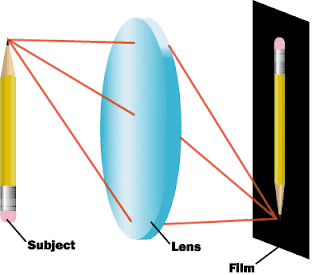
RAY DIAGRAM OF A CONVEX OR CONVERGING LENS


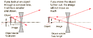
RAY DIAGRAM OF A CONCAVE OR DIVERGING LENS

RAY DIAGRAM OF A CONCAVE OR DIVERGING LENS


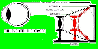
THE EYE AND THE CAMERA

THE EYE AND THE CAMERA


Light is excluded or permitted to enter by the eyelids, the equivalent of the camera shutter. The iris contains the variable opening, the pupil which regulates the amount of light entering and is the aperture of a camera. The diaphragm contains the aperture of the camera, so it is similar to the iris, which contains the pupil. The lens of the eye is a biconcave, transparent structure which is responsible for focusing. The innermost coat, the retina, lies behind the lens. It contains the optic disk, or blind spot, which is the junction of nerve fibers passing to the brain. It is the counterpart of the film in a camera. The film stores the photographic chemical record of data. The lens of the camera draws the light into the camera and focuses it on the film plane. To prevent the blurring of images by internal reflection, the inner walls of the camera-- the choroid layer in a human eye-- are painted black.


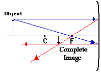
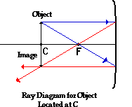
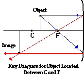
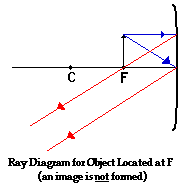
RAY DIAGRAMS OF A CONCAVE MIRROR


OBJECT BEYOND C


OBJECT AT C


OBJECT BETWEEN C AND F

OBJECT AT F


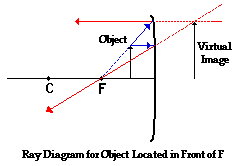
OBJECT LOCATED IN FRONT OF F


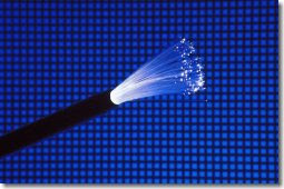
FIBER OPTICS


A relatively new technology, fiber optics is the channeled transmission of light through hair-thin glass fibers. The light is prevented from escaping the fiber by total internal reflection--a process that takes place when light ray travels through a medium with an index of refraction higher than that of the medium surrounding it. In this case, the fiber core has a higher refractive index than the material around the core, and light-hitting that material is reflected back into the core, where it continues to travel down the fiber.


Fiber-optic technology had its greatest impact in telecommunications, where optical fibers transmit audio, video, and data information as coded light pulses. In fact, fiber optics is rapidly becoming the preferred mode of transmitting communications of all kinds.


Its advantages over older methods include vastly increased carrying capacity(due to the very high frequency of light), lower transmission losses, lower cost of basic materials, smaller cable size, and almost complete immunity from stray electrical fields(interference).


Tuesday, July 31, 2007 ♥
Convex and Concave

The Mirror Equation


Ray diagrams can be used to determine the image location, size, orientation and type of image formed of

objects when placed at a given location in front of a concave mirror. The use of these diagrams were demonstrated earlier in Lesson 3. Ray diagrams provide useful information about object-image relationships, yet fail to provide the information in a quantitative form. While a ray diagram may help one determine the approximate location and size of the image, it will not provide numerical information about image distance and object size. To obtain this type of numerical information, it is necessary to use the Mirror equation and the Magnification equation. The mirror equation expresses the quantitative relationship between the object distance (do), the image distance (di), and the focal length (f). The equation is stated as follows:

The Magnification equation relates the ratio of the image distance and object distance to the ratio of the image height (hi) and object height (ho). The magnification equation is stated as follows:

These two equations can be combined to yield information about the image distance and image height if the object distance, object height, and focal length are known.


Thursday, July 12, 2007 ♥
LONG TEST

THE LONG TEST IS SO DIFFICULT..I HOPE I GET PASSING SCORE..T_T


welcome

©[markalvindelacruz.blogspot.com]

take nothing but memories
leave nothing but a lovely tag

profile

:D

my name is MARK ALVIN DELA CRUZ-
III-LINNAEUS/ VICE PRESIDENT
LOVES DENISE LOPEZ.

Photo Sharing and Video Hosting at Photobucket

credits
**xyra ianne yuson :D :B :O :P :X

archives
June 2007
July 2007
August 2007